Counterpoise Wire (AKA Rat Tail):
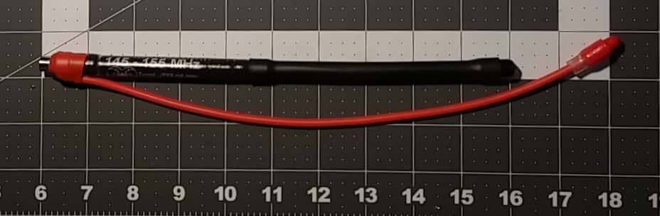
12 AWG SMA-M VHF Rat Tail on IPX6-F Antenna
A simple but significant, and inexpensive improvement that can be made to the Smiley HT antenna SMA-F and SMA-M bases we sell is the addition of counterpoise from a device commonly referred to as a "Rat Tail". The effectiveness of a counterpoise element is not a myth, it is pretty simple science and therefore not about to make anyone millions. Technically, counterpoise is is not a true ground plane, it would more accurately be referred to as a 'virtual ground plane'. You may have seen radial elements at the bottom of a base station antenna on a roof somewhere, and these are there to give counterpoise. So in the case of a rubber duck, counterpoise gives a virtual ground plane reference to trampoline the signal using the same dynamics analogous to what radials do for base station antennas.
First it worth noting that while a half wave antenna does not require a ground plane, an antenna that can reference a ground plane such as a 5/8 wave has better propagation. Our 5/8 wave is a base loaded 1/4 wave that radiates a 5/8 radiation pattern. That fact is germane to the antennas we stock. There are a number of videos in our Youtbe channel that illustrate the effect of adding a counterpoise wire to the various styles of antennas.
We have found subsequent to subjective field testing in environments where Guides often find themselves: on water, ice/snow, or porous regolith, means the ground you're standing on often acts as a poor capacitor with regards to your radio signal. Thus the counterpoise element can increase your transmit range exponentially because it introduces the all important ground reference that is needed for efficient signal propagation required by the vertical tuned element in monopole antennas. Our users have also reported they have seen a significant improvement in receive after deploying a Rat Tail as well.
We make these using silicon covered #10 or #12 AWG stranded copper wire, and soldered to a nickel strip that is spot welded to the metal Smiley base. The #10 is larger and heavier, but more closely matches impedence and yields better SWR. This MOD is compatible with your antenna and can be left on during travel and used when required, so you do not have to keep switching the base. The silicon jacket has superior flex, durability and cold weather performance compared to normal PVC coated wire. And more importantly, it is an insulation material that keeps the capacitive losses to the system at a minimum. Instead of being clamped to the outer collar of the SMA connector on your HT antenna, ours are soldered to prevent attenuation and loss introduced by a clip and acts as a counterpoise so that RF from the HT doesn’t couple with your body. We make 2M Tiger Tails suitable for use with our rubber ducks and they are highly recommended for use where you need maximum range from your antenna. Our Rat weighs 25 grams, and is compatible with all the antennas, so it can be used with any of them. This is a 'must have' for backcountry travel, and a mandatory piece of kit if you are a guide or may be the one that has to summon assistance via radio.
SWR Profile, 150 IPX6 without counterpoise (click image for larger view):

SWR Profile, 150 IPX6 with VHF 10AWG counterpoise (tip held @ 65 degrees above horizontal):

SWR Profile, 150 IPX6 with VHF 12AWG counterpoise (tip held @ 65 degrees above horizontal). Note diffrence in impedance:

Some general observations about the effects of counterpoise on the IPX6 antennas:
"Big Signals are not an accident. They are the result of good antennas."
Without counterpoise, the average impedance of the IPX6 when connected is 60 ohms. When counterpoise is added and held at the correct angle of 65 degrees above horizontal, the average impedance changes to 50. Why is it important to match impedance? The total impedance at the antenna terminals is the sum of the radiation resistance and loss resistance. Ideally, an antenna will represent a resistive load of 50 ohms as far as radio frequency energy is concerned so that all the energy is "lost" as radio waves propagated into space. Without the proper impedance matching, reflections can exist along the path from the source to the load. Our goal with impedance matching is to make the load impedance seem to look like the source impedance. To achieve efficient signal transfer, we need to hit a characteristic impedance target of 50-Ω impedance—the sweet spot for efficient signal transfer. Matching the impedances throughout the circuit yields a desired low voltage standing wave ratio (VSWR). Low VSWR circuits transfer the maximum amount of power from the source to the load.
Position of counterpoise: the best position is about 65 degrees from the horizontal plane. As you move the wire down toward the horizontal plane, the impedance rises, and optimal SWR frequency shifts about 5MHz higher.
The average difference to SWR between counterpoise and no counterpoise at the resonant frequency is about .4 For example, a 5 watt radio that has a 1.5 SWR will transmit with a forward power of about 4.75 watts. With a 1.1 SWR it will be about 4.97 watts. Therefore counterpoise can add an additional .22 watts to the forward power output. The gain in propagation depends of a wide variety of factors, but a seat of the pants guideline for what advantage this might give someone in the field with line of sight is in the neighbourhood of 400 meters.
The reflected energy - contrary to what some may believe (and what we previously stated on this website) - does not go back into the transceiver and damage it, but rather will change the voltage and current at the transceiver output connector. This means the impedance at this point may be vastly different from 50 ohms resistive, and so the output stage will be trying to dump energy into something it has not been designed for. This will either cause the output stage to draw excessive current, or voltage, with resultant damage.
